Layer Delineation
Most of the design problems encountered in Soil Mechanics involve calculations with geotechnical properties of soil profiles that have been deduced from raw geotechnical data. Case in point, recommended step-by-step design procedures within FHWA GEC 012 start by delineating the soil profile into layers using soil test data.
Overview
The process of delineating the soil profile into layers is easier said than done and is based on engineering judgement and experience. Figure 1 shows the SPT N values collected during field tests for “North Abutment S-1” (after FHWA GEC 012).
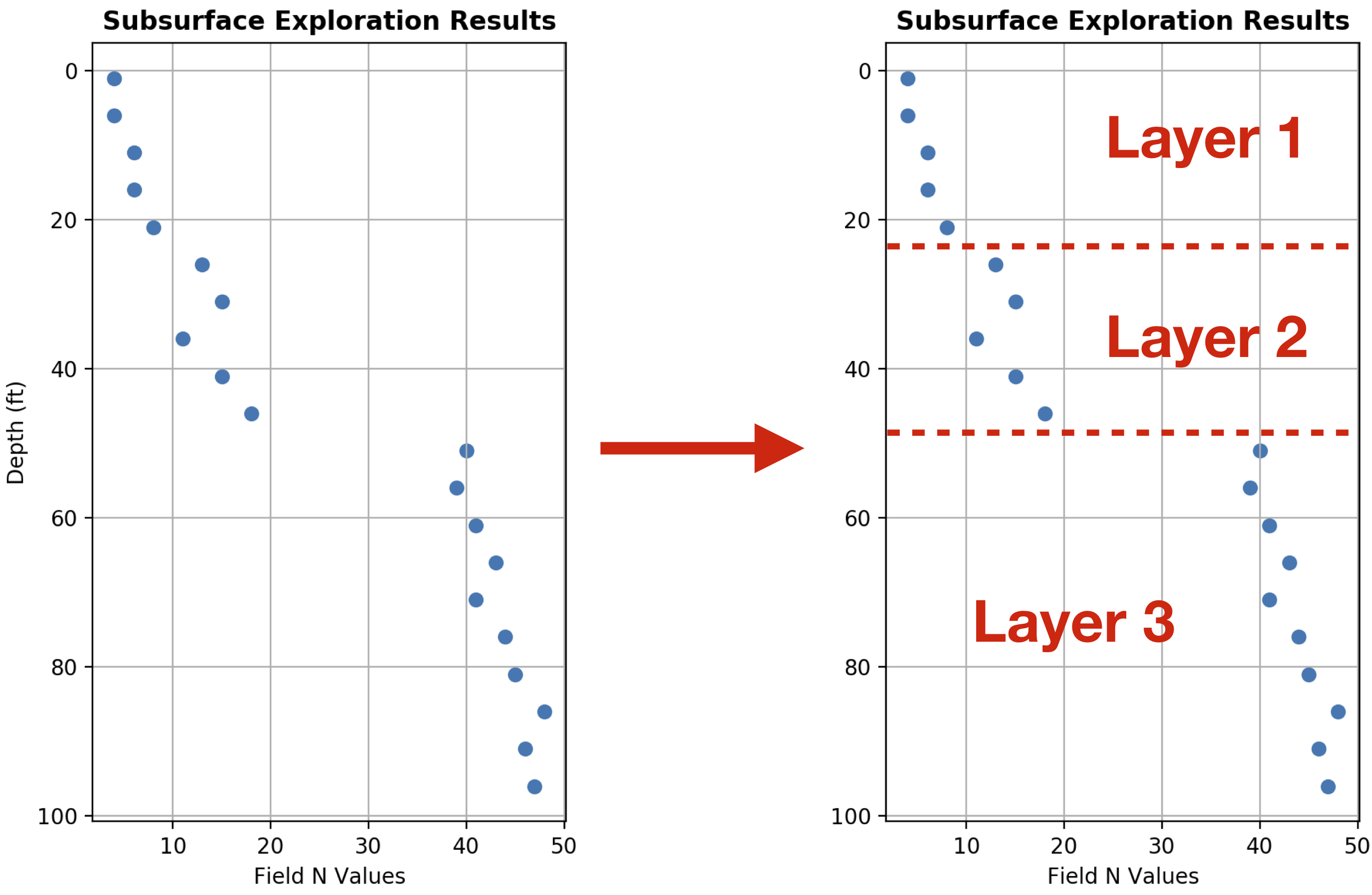
Figure 1 Delineating the soil profile into layers using the field SPT N Values for “North Abutment S-1” (after FHWA GEC 012).
There is no standard process for layer delineation. In the left-hand side of Figure 1, the field SPT N values are plotted with depth. There is an obvious “jump” in the N values at a depth of about 48 feet. This is indicative of a change in soil conditions, hence, delineating in two layers at this interface is reasonable. However, the change at depth 23 ft. is not as apparent based on N values alone. In such cases the N values are corroborated with other information obtained during subsurface investigations such as sample color, texture and geotechnical properties.
Note
The discussion in this section is not limited to field N values. The concept of varying soil conditions with depth extends to other geotechnical properties including internal angle of friction, φ, unit weight, γ, undrained shear strength, su, and more.
It is common practice that after layers have been delineated within a soil profile, the geotechnical properties for each layer are derived by averaging the available data for each layer. Table 1 offers an example of this process for “North Abutment S-1”.
| Depth (ft) | Field N Value | Soil Layer | Average N Value |
|---|---|---|---|
| 1 | 4 | 1 | 6 |
| 6 | 4 | ||
| 11 | 6 | ||
| 16 | 6 | ||
| 21 | 8 | ||
| 26 | 13 | 2 | 14 |
| 31 | 15 | ||
| 36 | 11 | ||
| 41 | 15 | ||
| 46 | 18 | ||
| 51 | 40 | 3 | 43 |
| 56 | 39 | ||
| 61 | 41 | ||
| 66 | 43 | ||
| 71 | 41 | ||
| 76 | 44 | ||
| 81 | 45 | ||
| 86 | 48 | ||
| 91 | 46 | ||
| 96 | 47 |
Hint
Average N values must always be rounded to an integer number.
Implementation in edafos
The average values of the geotechnical properties are used in design and other calculations with very few exceptions. This approximation is convenient for hand calculations but not necessary in algorithmic analyses.